A Simple Process for Designing Practical Objects in OpenSCAD
3D Printing Practical Items, Overview of A Process
I’ve been using OpenSCAD to create things to 3D-print for years now, and it can be a simple and fulfilling process to build up something useful from simple geometric primitives.
OpenSCAD is a “programmer’s CAD” where the models are written up in text, a bit like a program, and rendered as needed. There are a variety of geometric primitives available to the user that can be built up into more complicated modules. It allows for natural parameterization and I strongly prefer the simplicity of it to GUI-driven tools like AutoCAD, largely because by making the right choices
This post will cover:
- Gathering requirements for an object
- Making a sketch
- Rough Arrangement in Space
- Identifying critical dimensions
- Breaking down the model into smaller and smaller parts
- Writing up the OpenSCAD model
- Basic Testing in OpenSCAD
- Printing and testing in the Real World
Gathering Requirements
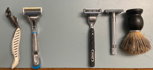
So there’s a bunch of things in the shower area that could be hung up. I’m talking razors and a brush. There are four razors and two brushes, both a bit different.
I want to use command strips to affix a holder or holders to a part of the shower, and then have it so that razors can be placed onto C-shaped grabbers instead of being scattered about the shower taking up precious space. I want to size the inner diameter to roughly correspond to each razor. It would be ideal to have it be snug, but not requiring force to bend the plastic back and forth.
If I decided to have all of them on a common backing I would have to consider grouping the razors together in some way. However, since each razor and brush is a little different, it will be easier to print a holder per item.
In my humble opinion, when creating practical objects that need to fit nicely, it’s nicer to work towards a simple, parameterized core that can be adapted for as many of the cases as possible. This is partly because I’m lazy and mostly because wasting filament is bad. If I needed to have a common backing I’d probably go through and make some prototype for the fitted sections so that the material needed for a common backing would not be wasted in multiple attempts.
Making a Sketch
Try drawing a rough image of the constituent elements and get thinking about how things will come together. Do not worry about how you would code it up or get clever at this point, just draw a few things and see what comes up.
I first drew a common backing, and spaced the holders evenly. If there was a common backing, it would be importand that the razor holders are far enough apart so that the razors don’t bump into one another. There are other thoughts that come up when sketching, such as that the holders can’t be too tall since most of the razors have a varied shape along the length, and the inner diameter and possibly the shape in the middle has to be reasonable enough to meet the snugness requirement.
The process of drawing is helpful to quickly remove the vaguaries of a purely mental picture, and it allows you to start asking focused questions about the design in question.
It is also generally cheaper and faster to tinker on paper than it is with a long string of failed physical prototypes.
Rough Arrangement in Space
If possible, arranging the objects or other prototype items is able to help provide additional insights. For one, gnolling the items in question revealed that the razors each have a bit of a height offset. If the common backing was preferred, it might be nice to try to align the business ends of the razors to be at the same height, this would mean the clamps would be higer and lower along the common backing, or noting that seperate holders would have to be placed at various heights.
The combination of a sketch and manipulating the objects is valuable to test assumptions and work out important details.
Identifying critical dimensions
After creating a sketch, I was able to identify some dimensions that were important and that I would have to measure out.
So the dimensions I noted as being important are:
- The specific diameter of the razors
- The minimum gap between any two razors (be equal to the span of the longest razor)
- The “height” of the holders
- The “height” of the brush-holder
- The dimensions of command strips
There are other dimensions to think about, such as the per-user gap considered earlier.
There’s also the possible dimesnions of a chamfer on the inner part of the holders, which could have an angle that I would like to match up with the razors of my roommate that have a “V” shape that connects to the business end.
There’s also the thickness of the holder parts themselves, but when it comes to these various elements, there’s a frugality to limiting the material used to accomplish the task to be balanced against a need for ruggedness for long-term use. Each holder has to take a static force of the weight of the razor, which is probably trivial. But if the user is trying to force a large razor into a smaller razor slot, how beefy should the C-clamp connect to the backing that is to go up against the wall?
For a design that is likely to have to deal with a heavy static loads (i.e a sledgehammer) or has to deal with dynamic loading, the object might need to have a shape that allows more a more complete connection. Strength is proportional to the areas that intersect.
If in the process of sussing out these critical dimensions, feel free to redraw the sketch with any new details. It is generally quicker to sketch it than to put things together in OpenSCAD, and it helps to make any mistakes very obvious if there’s a rough image in mind when going on to create the model.
Breaking up the model into smaller parts
I determined I could break down the design into three different parts, possibly four.
- The backing
- The C-shaped holders for a razor
- A spoon-shape for the round scrubbing brush
- Possibly: a unique holder for the shaving cream brush
The holders for the four razors will all be derived from the same module. The holder for the brush might be shorter in height and so there’s a possibility I’ll do something different for that, but it will be similar to the other parts, so perhaps I can get away with using the razor module with some different parameters.
We could try to have all the clamps go onto a single backing, but for the sake of simplicity, I’ll be creating independent holders with their own backings rather than all the holders on one backing.
Writing up the OpenSCAD model
Now that we know what the final product will look like, have an idea of what success looks like, and we know some important values, I am ready to code up the smaller parts.
Backing and hull()
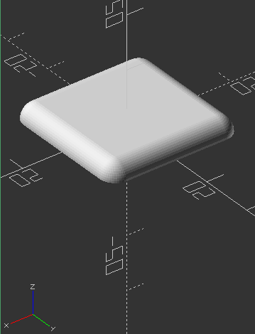
Let’s start with the backing. It will be rectangular, but I want the edge to not be sharp. To make the bevel, I can use the hull() function. A simple way to describe what the hull() function does is to imagine that it takes in whatever objects and covers them all in shrink-wrap. The result is a single object whose outer boundaries are defined by the objects involved.
In the below snippet, points are defined that are the distance equal to the width of the command strip sticky tape. opencad can iterate through a list of points with a for-loop.
At those points, I have half-spheres centered with some radius and use the hull() function to tie it all together.
1
2
3
4
5
6
7
8
9
10
11
12
13
14
15
16
17
18
19
20
21
22
23
24
25
26
27
28
29
30
31
cmdstrip_x = 69.31;
cmdstrip_y = 19;

corner_points = [ [-(cmdstrip_y)/2, -(cmdstrip_y)/2,  0]
                [   (cmdstrip_y)/2, -(cmdstrip_y)/2,  0]
                [  -(cmdstrip_y)/2,  (cmdstrip_y)/2,  0]
                [   (cmdstrip_y)/2,  (cmdstrip_y)/2,  0] ];

global_fn = 50;

module half_sphere(radius=2) // default radius of 2mm
{
  diam = 2*radius;
  difference()
  {
    sphere(r=radius, $fn = global_fn);
    translate([-radius, -radius, -diam])
      cube([diam, diam, diam]);
  }
}

module backing(points)
{
  hull()
  {
     for(p = points)
      translate(p) half_sphere(radius = 3);
  }
}

backing(corner_points);
The hull function with a bunch of half-sphere creates the following flat-backed object that is free of sharp edges!
Holder
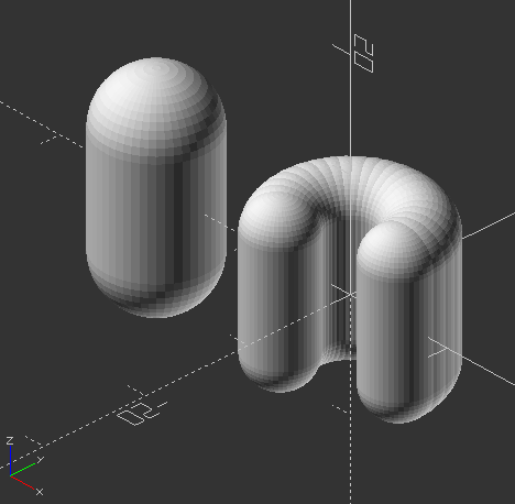
To make a C-shaped section, we can use a for-loop to rotate an object some radius from the center. This allows us to define the opening in terms of degrees. If we used a cube() form that went the full 360 degrees, then we would have a cylinder with a cylindrical hole. Again, to avoid sharp edges, the form that will be dragged around in space will be a capsule, which is a cylinder with spheres at the end.
To create the C-shape, we rotate the object and then have it be translated out by the radius as provided by the argument
1
2
3
4
5
6
7
8
9
10
11
12
13
14
15
16
17
18
19
20
21
22
23
24
25
module capsule(radius=15, h=30)
{
  hull()
  {
    translate([0, 0, h/2])
      sphere(r = radius, $center = true, $fn=global_fn);
    translate([0, 0, -h/2])
      sphere(r = radius, $center = true, $fn=global_fn);
  }
}

module clamp(radius=5, thickness=3, height=10, degrees=220)
{
    max_i = round(degrees/10);

    for(i = [0 : 1 : max_i])
    {
      rotate([0,0,i*10])
      translate([radius, 0, 0])
        capsule(thickness, height);
    }
}

translate([-20,0,0]) capsule();
clamp();
The above snippet will let you make a pill-shaped object and then to turn that into a C-shaped clamp.
Bringing it together
We can now combine the backing and the clamp. However, we have a problem if we just try to have the backing be the clamp radius away from the center of the C-clamp. What we can do is consider the degrees argument that we send to the clamp, divide it by two, and then do our operations:
1
2
3
4
5
6
7
8
9
10
11
12
13
module razor_holder(radius=10, thickness=3, height=10, degrees,
backing_points, backing_h = 3)
{
clamp(radius - thickness, thickness, height, degrees);
rotate([0,0,degrees/2])
translate([radius+backing_h/2,0,0])
rotate([0,-90,0])
backing(backing_points, backing_h);
}
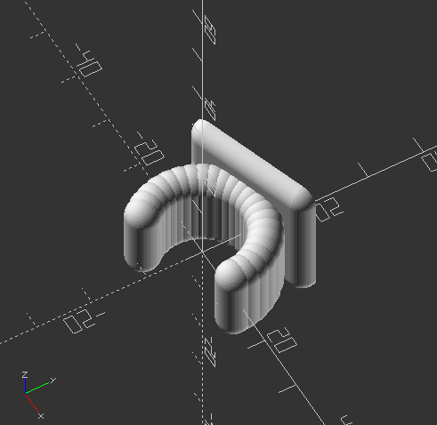
razor_holder(10, 3, 10, 220, corner_points, 3);
Here’s a happy rendering of a razor-holder able to hold one razor that’s 10mm in diameter at the point where we want it to be held.
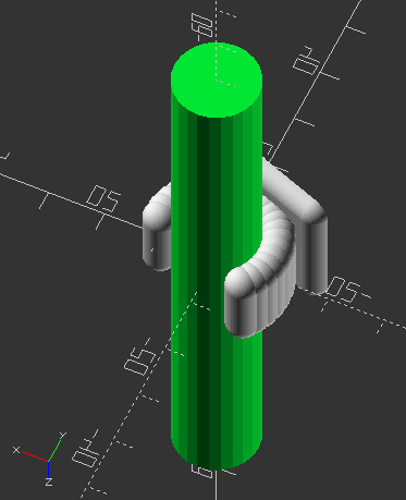
Before printing, a quick check can be done. Since the diameters of the various razors and brushes were mesured, we can put in a cylinder after the razor_holder() call and see what actually will fit in the holder.
I highly reccommend a little bit of checking with some of those previously measured critical dimensions. The first argument to our function was originally not exactly the inner radius, as the body of rotation has its own thickness, so the available space is the radius minus the thickness of our holder. That’s why the clamp() called in razor_holder() takes the radius argument and subtracts the thickness argument.
In more complicated models the various operations can result in errors of various sorts that a quick check such as this can expose. With parameterization you can tweak yourself out of these error situations, but use judgement on refactoring a model if the tweaking process is cumbersome or confusing. If you start to internalize the dialing-in process with the test, then you might as well just fold that into the model, yeah? But if it’s a single-purpose item or an artsy piece that doesn’t require re-use and adjustment, then don’t break your back trying to make the model beautifully and intuitively parameterized.
Also in more complicated models, where there are many critital dimensions, having a more complete set of “dummy” parts or as a whole separate module not intended to be printed can be added to the preview (but not rendered) to check if the requirements are met or if more changes are needed. This can be helpful to also spot unusual coupling where adjusting one thing causes “surprise” changes somewhere else.
1
2
3
/* A simple test, for OpenSCAD objects */
color([0,0.9,0.2])
cylinder(h=100,d=15, center=true);
If the output doesn’t look right, but a few adjustments of the input parameters get you there, but if the item in question is going to be re-used a lot, then it might be worth revisiting the model so that the inputs aren’t belying a surprise or two. For example, we could have the radius argument be summed with the thickness (radius of the C-shaped clamp) so the input for the clamp radius is truly the clamp radius.
Since I’m happy with this output knowing that it will match a razor, it’s time to render (hotkey F6) and then export the rendering to an STL (hotkey F7). Rendering takes a while because of the way we’ve created multiple hull objects and iterated over them in a for-loop. You can adjust the step size per degree (as long as the maximum number of iterations is also updated) to create a lower “resolution”, or go the other way and increase the number of iterations and lower the rotation associated with each step to create a higher resolution volume of rotation.
In prusaslicer, we can use Place on Face (hotkey F) and select the backing as “face-down” for printing.
Fire away with the desired material and a low-ish infill (and potentially enjoy the little problems that come upkwith 3D printing anything in general). The result matching the white-bodied razor is shown below:

I can now create holders for most of the razors and brushes, with the exception of the other brush with a round shape (not pictured above). For that I can have a disk (cylinder) “minus” a sphere where the radius is equal to the radius of the brush body. It would a bit like a simple spoon shape, and then combine that to the backing with perhaps a rectangular arrangement of points since it’s 6cm across.
Conclusion
The process for creating a practical object can be a bit iterative and frustrating, but each step can be figured out incrementally to produce the final model. By first prototyping with sketches, you can work out some important dimensions or constraints to work with. If you can do stuff in physical space you can arrange objects, trace outlines, and make measurements of things as you have arranged them.
After getting a sense of what the final end piece is, break down the model into smaller modules and work out each of them in turn. Once the elements are built up, bring these elements together.
If the small parts are more or less where they need to be, then the integration step can be smoother than trying to design and integrate many different parts all at the same time.
Once the model has been made, a few final checks can easily be done with “dummy” models representing critial dimensions. This might be one object like the cylinder-check for this object, or it can be a whole virtual jig.
If the final checks and tweaks look good, then it’s on to printing the object(s). Happy designing and printing!